|
There are many devices that can do this operation. This is by far one of the least expensive and smallest packages on the market. The RIGblaster nomic draws its power through the serial port from the computer which eliminates a power cable. Besides providing power the serial cable is what keys the transmitter using RTS or DTR. It also passes the audio to the radio microphone using the computer line out audio jack on larger computers or the ear phone jack on laptops. The nomic comes with all the required cables plus several types of microphone cables that will fit any radio that uses a modular plug or the round 8 pin type. There is a audio level control that should be set to mid range on most systems.
|
|
Below is a picture of the RIGBlaster nomic internals. There are set of jumpers that allows you to configure this device to any radio sold on the market. Pins 1 through 8 represent the microphone connection to the radio. These connections do not connect to anything until you jumper them. Since a particular type radio defines the function of what pin 1 through 8 is used for these will have to be configured for each type of radio attached. The other connections such as MIC, MIC GND, GNDTIE, PTT GND and PTT are connections to your computer hardware. The nomic manual that is supplied does have some of the more common radio configurations but you may have to refer to you owners manual for the microphone pin out. Audio out jack is for a set of ear phones so you can listen to the audio that is being sent by the computer. This connection can be pretty much ignored. A copy of the nomic manual is provided here to help with the pin configuration with most common radios.
|
|
Connecting the nomic and the radio to your computer is very simple. Connect the speaker output of the radio to the line input jack on the computer. The headphone or speaker output jack is connected to the nomic audio input. The RS-232 connector connects to one of the serial ports on the back of the computer and to the serial in port on the nomic. The serial connection is what controls the PTT line.
|
|
Yaesu FT-847 shown with the microphone connection to the nomic. Be sure you turn off the Compression, Notch Filter, Noise Blanker or Noise Reduction options. These will cause problems using any of the digital modes. Also never run your radio over half the rated power level of the radio or you will burn it up. Your radio is not radio for continuous duty.
|
|
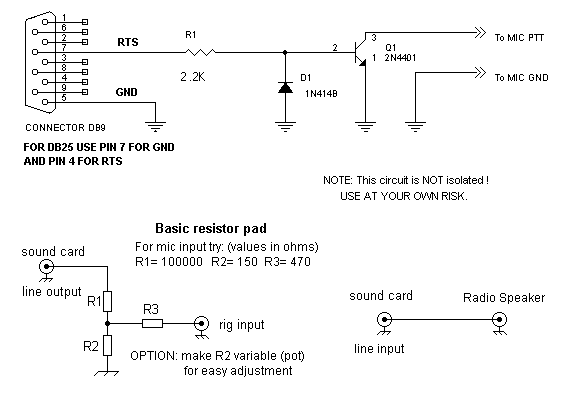
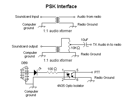
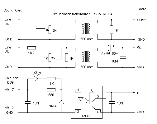
For those who rather build things than buy them. Here are a few examples of a simplified computer interface. There are many others out there that are better than these examples. There is no isolation or impedance matching in example 1, but it will get the job done.
|


